Custom Metal Fabrication Shop
Overview
Preserved shop record for cliftonprecision.com. The former plant is not quoting from this domain. The preserved pages read like a shop that organized itself around three connected capabilities: machining, presswork, and laser scanning. The navigation itself tells the story. A visitor moved between Tools, Machining, Presswork, Laser Scanning, Low Cost Resources, and Industries. Under Industries the pages list Aerospace, Automotive, and White Goods, with other pages adding National Heritage, Medical, Motorsport, and Leisure. That range matters because it describes the kind of custom metal fabrication shop that does not treat one material or one sector as the whole of its work. The shop language is practical and specific: one-offs and bespoke developments, small batch work, prototype to final production, traditional skills and craftsmanship supported by high technological expertise. The m
Details
achining pages describe capacity in plain terms. There are two well equipped CNC machining shops with surface grinders, optical profile grinders, lathes, and manual milling machines supporting eight full 3D CNC machining centres. The largest travel range reaches 4 metres by 2.5 metres by 1.25 metres, with a weight capacity up to twenty tonnes. Elsewhere the record notes six CNC Hurco machining centres with Ultimax software and a travel range of 1700 x 600 x 500, one Zayer CNC machining centre with Heidenhain 426 control and a travel range of 4000 x 2500 x 1500, and one Fil CNC machining centre with Heidenhain 426 control and a travel range of 2000 x 1000 x 1000. The Hurco page mentions 24 hour machining capacity on eight Hurco machining centres, capacity up to 1.7m x 0.6m x 0.5m, and a set-up specialising in one-offs and bespoke developments and small batch work. All CNC machines are fully networked and linked to the CAD CAM office for direct data transfer, using a DXF translator for programming direct from tool drawings. That is the process language of a custom metal fabrication shop: the drawing goes to the machine, the set-up is built for the job, and the work is proved out before it becomes a batch. The preserved pages also name the software environment. NC Graphics toolmaker 2D/3D software for tool design and 3D surface manipulation. Machining Strategist as a 3D machining package. AutoCAD 2000. Rhino 3D for solid modelling and 3D surface manipulation. Optris virtual press simulation solver software for die development and stress analysis. Ficture graphical user environment manager. PAM DieMaker interactive die addendum creation software for quick modification within the stress analysis software. Renishaw 3D scan software for full reverse engineering capabilities. The shop did not separate design from making. It kept the CAD CAM office linked to the floor. Presswork and tooling run through the same record. The pages describe press tool manufacturers, die development, stress analysis, and die addendum creation. Electrode discharge machining appears as a complete range of high precision work, including five Charmilles Robofil EDM machining centres, a Charmilles Roboform EDM sparker, and a Charmilles deep hole sparker eroder. The CNC machining page mentions 2/2.5D wiring and sparking using the NC Graphics programming system, and five CNC Charmilles tec robofil sparker eroder including 2000/4000/6000 and the new 510, with capacity ranging from 320x220x350 to 700x. The Zayer page calls the shop Specialists In Press Tool Manufacturers and names a Zayer Machining Sparker Eroder. These are not separate services bolted onto a general machine shop. They are the toolroom sequence: mill the form, burn the detail, wire the profile, prove the die, and support the press. The laser scanning page adds the measuring and capture side. The latest investment was a Laser Arm Scanner, a portable device offering a wide range of services. Reverse engineering creates accurate digital models of existing components, re-designs and re-engineers parts, or captures hand-worked changes for CAD. Quality inspection compares accurate digital models with CAD to ensure products meet intended design. The machining page says the scanner is used in conjunction with rapid prototyping. That closes the loop between an existing part, a digital model, a machined or formed component, and an inspection check. For a custom metal fabrication shop, that loop is the difference between copying a sample and controlling a process. The materials list is broad: aerospace materials, plastics, polystyrene, model board, tool steels, wood, and marble. The markets list is equally broad: Aerospace, National Heritage, Medical, Automotive, Motorsport, White Goods, and Leisure. A shop that cuts tool steel for a press die and also machines model board for a prototype is set up to move between hard tooling and soft proving. The preserved pages say the company works closely with customers at all stages of new product development from prototype to final production, which ensures the most cost effective solution is achieved. They also say today's premier press tool manufacturers demand a combination of outstanding traditional skills and craftsmanship supported by high technological expertise and project management techniques. The record does not quote prices, does not present an RFQ form, and does not claim certifications. It describes machines, controls, software, capacities, materials, and industries. The custom metal fabrication shop that emerges from these pages is a toolroom and machining plant with presswork at its centre, scanning and reverse engineering at its edges, and a CAD CAM office networked to the floor. The work moves from drawing to set-up, from one-off to small batch, from hand-worked change to digital model, and from die development to production. That is the process language preserved here.
Drill size reference
| Drill | Decimal inch | Millimetres |
|---|---|---|
| #1 | 0.2280 | 5.791 |
| #7 | 0.2010 | 5.105 |
| #13 | 0.1850 | 4.699 |
| #21 | 0.1590 | 4.039 |
| #29 | 0.1360 | 3.454 |
| #36 | 0.1065 | 2.705 |
| #43 | 0.0890 | 2.261 |
| #53 | 0.0595 | 1.511 |
| 1/16 | 0.0625 | 1.587 |
| 5/64 | 0.0781 | 1.984 |
| 3/32 | 0.0938 | 2.381 |
| 7/64 | 0.1094 | 2.778 |
| 1/8 | 0.1250 | 3.175 |
| 9/64 | 0.1406 | 3.572 |
| 5/32 | 0.1562 | 3.969 |
| 11/64 | 0.1719 | 4.366 |
| 3/16 | 0.1875 | 4.763 |
| 13/64 | 0.2031 | 5.159 |
| 7/32 | 0.2188 | 5.556 |
| 15/64 | 0.2344 | 5.953 |
| 1/4 | 0.2500 | 6.350 |
| 5/16 | 0.3125 | 7.938 |
| 3/8 | 0.3750 | 9.525 |
| 7/16 | 0.4375 | 11.113 |
| 1/2 | 0.5000 | 12.700 |
| F | 0.2570 | 6.528 |
| H | 0.2660 | 6.756 |
| L | 0.2900 | 7.366 |
| P | 0.3230 | 8.204 |
| S | 0.3480 | 8.839 |
| W | 0.3860 | 9.804 |
| Z | 0.4130 | 10.490 |
Common questions
What is a #1 drill bit in inches and millimetres?
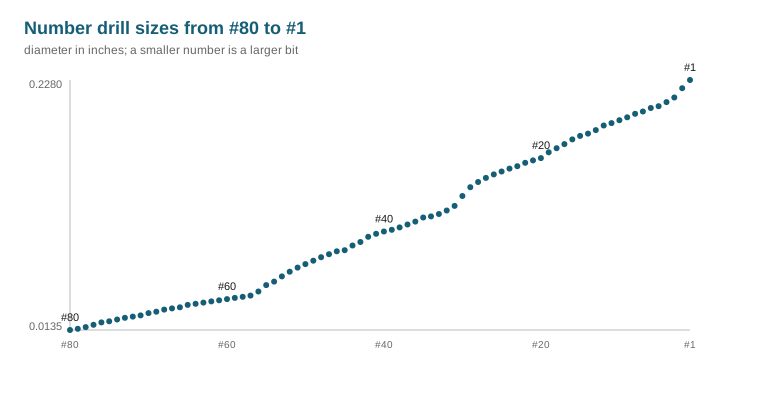
A #1 drill bit is 0.2280 in, which is 5.791 mm. Number drills run from #80 at 0.0135 in up to #1 at 0.2280 in, so a smaller number is always a larger bit.
What is a #7 drill bit in inches and millimetres?
A #7 drill bit is 0.2010 in, which is 5.105 mm. Number drills run from #80 at 0.0135 in up to #1 at 0.2280 in, so a smaller number is always a larger bit.
What is a #13 drill bit in inches and millimetres?
A #13 drill bit is 0.1850 in, which is 4.699 mm. Number drills run from #80 at 0.0135 in up to #1 at 0.2280 in, so a smaller number is always a larger bit.
This page is an archival note for informational purposes only. It does not offer representation, evaluate claims, or create a professional relationship.